The purpose of the first game is to illustrate how data transmission works, using the transmission of a small picture.
The purpose of the second game is to illustrate how the internet works, sending messages in small packets through routers.
The target age group is 8 to 12 years.
These two games are for a maximum of 30 children, split into several groups. The two games together occupy the children for an afternoon. It is highly recommended to have one adult helper per group plus an “animator” or activity leader present. We worked with a professional clown, who came dressed up as such.
To keep attention going, there should be some prizes to win.
The total budget is small, of the order of perhaps 10€ to 20€ (not counting the reusable code boxes)
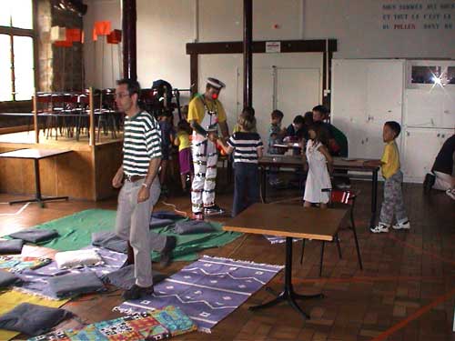
the clown, and adult helper and a group of kids on the first game
A fairly large room is needed, a classroom is probably too small but a hall or gym room is fine.
the room we used
The chairs that will be the routers (see later) in the second game are standing ready
on the platform, showing their name tags fixed to bamboo
marker sticks. The tape laying out the network is already stuck on the floor.
The children are divided into groups of minimum 2 and maximum 6 to 10.
Items needed:
a large room
two tables per group plus an extra table to display the tokens (see below)
1 chair per child
long sticks (1.5 to 2m, can be bamboo).
paper, pre-printed in several forms (see below)
one set of colour felt pens per group
adhesive tape, wide (min. 5cm) and preferably of a colour that contrasts with the floor; approx. 50m is needed.
scissors, office-type adhesive tape
sets of tokens, which are (small) objects such as model trucks, pencils, model trees, small hammers, toy animals etc. There should be as many tokens in each set as there are groups.
transmitter-receiver boxes, see below
separating screens if available
Game 1: Data Transmission
The first game gives an idea of how computers communicate data.
The children are divided into a number of teams. Each team is again divided in two groups: “transmitters” and “receivers”. The transmitters have to send pictures to the receivers over a data line, as explained below.
The first team accomplishing the task wins.
Explanation of the process
The transmitters and receivers of each team are sitting at two tables that are separated such that there can be no direct contact between them. Sit them at opposite ends of the room, or use a separating panel if available. Thus the teams have to use a device to communicate. Making the device needs some soldering skills, but is not difficult; the construction is explained below.
To make the game more interesting, we bought miniature representations of the objects depicted in the pictures, and displayed them on a table.
The pictures are a fairly crude rectangular grid of pixels, e.g. like this example representing a tree:
example of a picture
This tree is only 5x8 pixels big, but there is a sufficient number of pixels to recognise the object. All teams get the same picture to transmit. The transmitters know the object, but the receivers have no idea other than that it must be one of the objects on the table.
Each team has a box with two buttons and two lights (e.g. yellow and green). Pressing a button makes the corresponding light glow on both boxes. The boxes are linked by a long cable.
To transmit a picture, we use codes and procedures close to computer communication over serial links. We transmit each pixel in turn, from left to right and then top to bottom. We will use a code for the colour of each pixel, and a special code to signify the end of a row of pixels. Binary signals will be used. If we limit ourselves to seven colours plus the end-of-row code, then we need only 3 bits per code. For a more in-depth explanation of our choices see below.
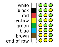
Given seven colours and the end-of-row, this is the colour code table we used:
code table
To transmit the 5x8 picture of the tree, the sending child would press the green (G) and yellow (Y) buttons on his/her box in this pattern:
GGG (pause) GGG (pause) YGG (pause) GGG (pause) GGG (pause) YYY (pause, and this is also the first row) GGG (pause) GGG (pause) etc. The clever ones of course discover that you don't have to transmit the white pixels at the end of a row, and this point could be used to explain how compression can reduce transmission times.
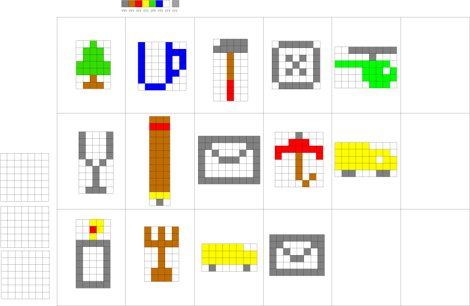
Here are some designs:
some designs for pictures
They represent a pine tree, a cup, a hammer, a die, a helicopter, a glass, a pencil, and envelope, an umbrella, a truck, a candle, a fork, another truck, another envelope.
To give everyone in each team something to do, we split the task into several steps. In the transmitter's group of a team, one child would use the code table and the picture to read out the code of each pixel to a second child who would fill in the codes on a strip of paper; a third would then get the strip and transmit the codes using the buttons. We used pre-printed strips of paper like this:
code strip
The others could watch and check, and at some point switch roles. Groups of 5 to 6 children seemed to work well. In the receiver's group, the inverse process would occur.
One trick we used to prevent the children from making an early guess was to colour the pixel in the bottom right corner with a colour chosen at random, and different for each team. It was then not enough that they found out which object was represented by the picture, they had to wait for the final pixel to arrive correctly. On the table we also had for each object as many copies as there were teams, with each copy labelled with a coloured dot corresponding to the colour of this last pixel.
In the session, we had a professional animator present, who would also make an assessment of the overall quality of the transmission. In the first few transmissions, many pixels get sent or interpreted incorrectly. The first picture should be simple and used to get the teams to “warm up”. The whole class tires of the process after about three pictures, i.e. the warm-up one and one for each side of a team.
Props required
A transmitter-receiver for each team. This is a battery-powered device consisting of two boxes with push buttons and lights. This item is the only one that requires some mechanical and electrical skills to make. Its construction is explained below.
A set of tokens, preferably small toys or other cheap things that may be given away. For each object there should be as many copies as there are teams. E.g. if four teams: four toy cars, four miniature plastic trees, four pencils, four dice, etc.
A set of code tables, two for each team.
A set of images, prepared in advance, representing the tokens. Since the images have only few pixels, the tokens should have very distinct and distinctive shapes.
A set of blank pages with a square grid on them, for the receivers to draw on.
A set of paper strips with a line of 24 little circles in groups of three.
A set of coloured felt pens for each team.
Tables and stools.
The device
The device consists of a cable with four wires, about 10 metres long, with a little box attached to each end. Each box has two buttons and two lights. The lights represent the two states of a binary bit.
To transmit a bit, in principle we only need to light up a lamp at the receiver's end by pressing a button on the transmitter's end. But that would give no feedback to the child pressing the button. We put lights and buttons at both ends, also making the whole device symmetric. The simplest schematic for this is:
schematic 1
Both lights go on whenever one of the two buttons is pressed.
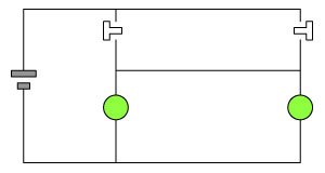
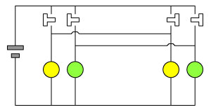
But we need two lights because we don't have a clock (see below), so it becomes:
schematic 2
The yellow lights go on when one button is pressed, the green ones when the other button is pressed.
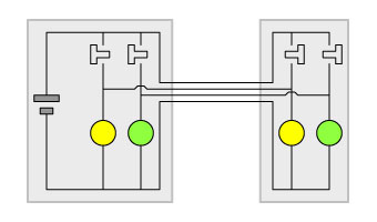
Finally, there should be a long cable between the two sets of buttons and lights, and the sets should be put into little boxes:
schematic 3
The cable between the boxes needs four wires. Flexible telephone cable has four wires and is cheaply available from most do-it-yourself stores.
If you use LED lights, a resistor needs to protect each LED. For a 9V battery, this would be between 100 Ohm and 200 Ohm. To make things even more professional, you can use RJ11 type phone sockets on the boxes and use RJ11 type telephone cable, so the boxes are detachable. It then looks like:
schematic 4
The cable between the boxes should be about 10m long.
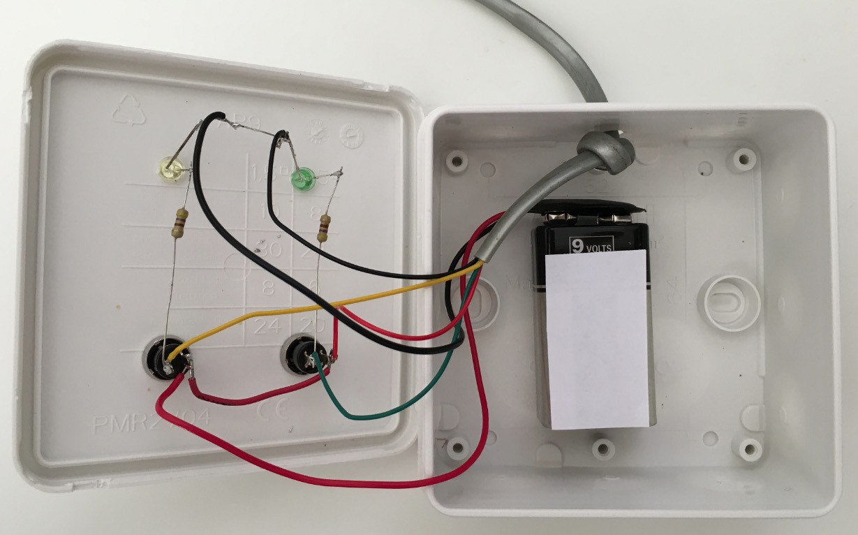
We found pushbuttons, 5mm yellow and green LEDs with resistors, 9V battery attachments and small electric connection boxes in a nearby DIY store. These are pictures of our devices:
outsideinside
The battery is an ordinary 9V battery, it is glued to the bottom of the box with double-sided adhesive tape. A knot in the cable prevents it from being pulled out. The soldering work is “spidery” and should be done better. To fix the LEDs in the cover, use a 4.8mm drill bit (not 5mm) to ensure there is enough friction to hold the LEDs firmly in place.
Some thoughts on the choices we made
Binary code transmission in real systems is accompanied by a “clock” signal: at each beat of the clock, the voltage on the cable is observed, if it is high, a binary “ON” or “1” is noted, if it is low, an “OFF” or “0” is noted.
However, we felt that this would be prohibitively complicated in the classroom: first, someone would have to “be the clock”, and secondly it forces a pace that some of the children may not be able to follow. When a child misses a clock beat, confusion sets in as to where to restart from etc. We also thought that using the clock-less Morse system of short and long bits was not child-proof enough (though note that neither claim has been verified experimentally!).
So we opted for a system whereby both ON and OFF states have their own button and their own light. We also thought it would be good not to confuse the children with such concepts as “0” and “1”, “binary numbers” etc. which are remnants of the jargon from the age when computers were primarily used for numeric calculations. We avoid even the use of “ON” and “OFF” and we simply chose colours that carry no (or little) meaning, such as yellow and green, expressly avoiding red/green.
We first thought of using a grid of fixed width and height for the images. But that again meant there had to be an implicit counter for switching to the next line. If one pixel gets lost, the whole picture becomes scrambled. The end-of-row code gives a more robust procedure. In addition, it allows us to use either pictures that are wide but not high (truck) or high but not wide (hammer, pencil).
Game 2: Packet Routing
This game shows how data travels over the Internet by simulating packet routing.
The children are assigned to one of two different tasks: a child is either a part of the network or a network user. The users form pairs, trying to send messages across the network in the form of “packets”. The first pair to transmit a message without errors wins. The network tries to deliver messages despite node failures.
The game uses a game leader, whose important task is to simulate network errors: he/she can disable network nodes at random for a certain time, grab packets on the fly to destroy them or block lines.
Messages are split into equal length chunks (packets) which are written onto numbered pieces of paper that have the destination name on them. These pieces travel the net like the real internet packets do: they are handed from node to node until they arrive at their destination. The reason they find their way is that each network node has a routing table that tells that node to which next node to hand it to, depending on the ultimate destination.
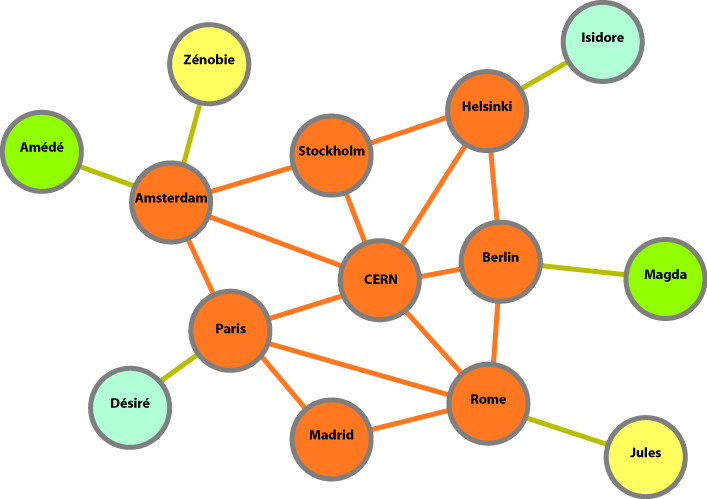
A set of chairs or small tables is used to represent the nodes of the Internet. They are “connected” by lines symbolised by the tape stuck to the floor. The user computers are on the rim of the net and have names of people while the nodes have names of cities.
network
There is an even number of users, they are teamed up in pairs, with the two sides of a pair being on opposite sides of the net (same colours in the diragram).
The children at the user “computers” will send messages by using “packets”: they first write out a complete message, then cut it up into chunks, write the chunks on pieces of paper and hand those to the children in the network nodes. The children in the network hand the pieces of paper from node to node until they arrive at their destination. The children at the destination have to assemble the pieces again into a complete message.
Because the game leader can disable a node at random, the children at the nodes will have to use their routing table to decide to which nodes to hand the pieces they receive. Example:
table
For example, the child at Paris will have a table which says that a piece of message destined for Magda should preferably go via CERN, but if that is not possible then via Madrid and as a third choice via Amsterdam. The table of the child at CERN will show that anything for Magda should be handed to Berlin as a first choice, and so on.
CAREFUL: suppose the node CERN goes out of order. Then Amsterdam can no longer use the first choice to go to Magda. If its second choice is Paris, then the second choice of Paris to go to Magda must not be Amsterdam, otherwise there is a loop! The real internet avoids such loops by noticing them, but you better have the routing tables set correctly for the children!
Each side of a team will send a message to the other side and at the same time receive the other side's message. If a packet goes missing because the game leader has destroyed it, the receiving end can send a message to ask for that packet to be sent again. Messages are necessarily terminated by an “end-of-message” packet.
Props required
A table for each node and for each user. There should be a chair for each child.
Message sheet: it has rows of boxes in which the letters of the entire message are written:
The rows are already separated into packets of five letters each, and show a number of the packet.
Packet papers: these are smaller pieces of paper each containing boxes for the sender, destination, message number, packet number and the letters of the packet.
End of Message packets and Packet Lost packets: these look like the packet papers but do not contain data:
They can be printed on coloured paper to add interest and to distinguish them better from normal packets.


